What Happens When You Type a URL and Press Enter?
Author
Elle J
Date
Mar. 1, 2021
Time to Read
28 min
Prerequisites
- ★Curiosity
Browsing the web is something many of us do every single day. We type the URL, press enter, and expect to see a beautiful website within a few seconds. But how is it that you can just ask for something (e.g. the content of a website) by typing it in a browser, have that question show up on the exact machine (possibly across the globe) that can answer it, then get a response and see the content on your screen before you even have time to take another sip of coffee?
A great scenario for understanding the extremely interesting concepts and mechanisms behind each step is to follow the message you send when typing https://www.ellej.dev in the address bar and pressing enter.
You will learn incredible things on this little journey such as:
- How devices talk to each other.
- What path a message takes from your computer to a server.
- What the Internet is.
- How a message transforms from a mouse click to electrical signals in a cable.
- How a message finds the exact destination.
- The purpose of protocols such as HTTP, DNS, TCP, IP, ARP, and Ethernet.
- Illustrative diagrams will help guide you throughout the article.
The first three sections will give you a good general understanding of the Internet without going into details such as protocols or headers. Thereafter, we dive a bit deeper into the even more interesting parts.
Table of Contents
Overview and Short Version
Web browsers such as Firefox and Chrome allow for an easy way for you and me to access various resources on the web. This type of interaction is usually referred to as a client-server architecture since the client (e.g. a browser) asks the server (e.g. the hardware where the resources are located) to get a certain file (e.g. index.html). To clarify, the homepage of websites is usually called index.html. So by default, https://www.ellej.dev is actually asking for https://www.ellej.dev/index.html.
However, there are essentially three things that need to happen (Step 1-3) before the client can ask the server for index.html (Step 4) after which they stop the communication (Step 5):
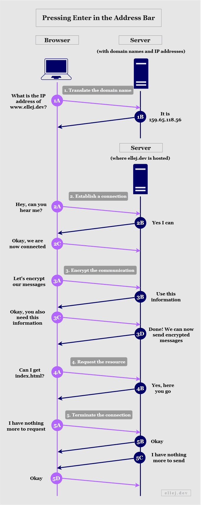
Let’s briefly go through the steps in the diagram above.
- Translate the domain name
- In order to locate the target machine (the server) we need to know its IP address. The domain name (ellej.dev) merely exists in order to make the addresses more humanly readable. Thus, the browser asks a server containing domain names and their respective IP addresses to return the IP address equivalent of ellej.dev.
- Establish a connection
- In order to be able to send messages back and forth between the client and server we first need to know if the server is even listening to our request. A server can be listening on various ports (you can think of doors) and if it is not listening to the door we are knocking on then we cannot communicate. The https part of the URL will indicate which door we are knocking on. If the client gets a response from the server, they can establish a reliable connection.
- Encrypt the communication
- Since we are typing https and not http we need to be able to encrypt the messages. The client and server exchange information needed to create certain encryption keys, after which the content of the messages will be unreadable to anyone but the two.
- Request the resources
- The client can now ask for index.html and if the server has that file it will return it. Oftentimes, a web page is not solely made up of one file. For instance, there may be multiple images to load as well. For each individual resource, the client makes an additional request, sometimes needing to first create a separate connection for each one.
- Terminate the connection
- The connection has been kept open during this communication, but when the client and server no longer need anything they let each other know and the connection terminates.
For each one-way arrow in the diagram, the message passes through several layers and transformations, the details of which are super interesting and will be explained thoroughly in the upcoming sections.
Overview of the Communication Devices
Currently, only two devices in the communication flow have been presented--your computer (containing the web browser) and the server. Those represent the endpoints of the communication. However, as you probably know from connecting to the Internet in your home, there are a few more devices involved in the process.
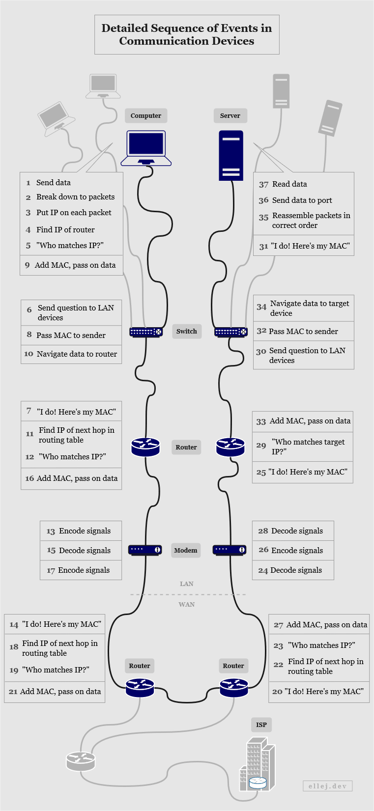
The diagram below walks you through the physical devices that each message passes through from your computer to the server (and vice versa). It also briefly states the responsibility of each device. Firstly, let me clarify four technical terms used:
- Network - Two or more connected computing devices or groups of devices.
- LAN (Local Area Network) - A network where the connected devices are in the same physical location. (E.g. your devices at home.)
- WAN (Wide Area Network) - A network connecting multiple LANs.
- ISP (Internet Service Provider) - A company that manages WANs and offers services to access other networks.
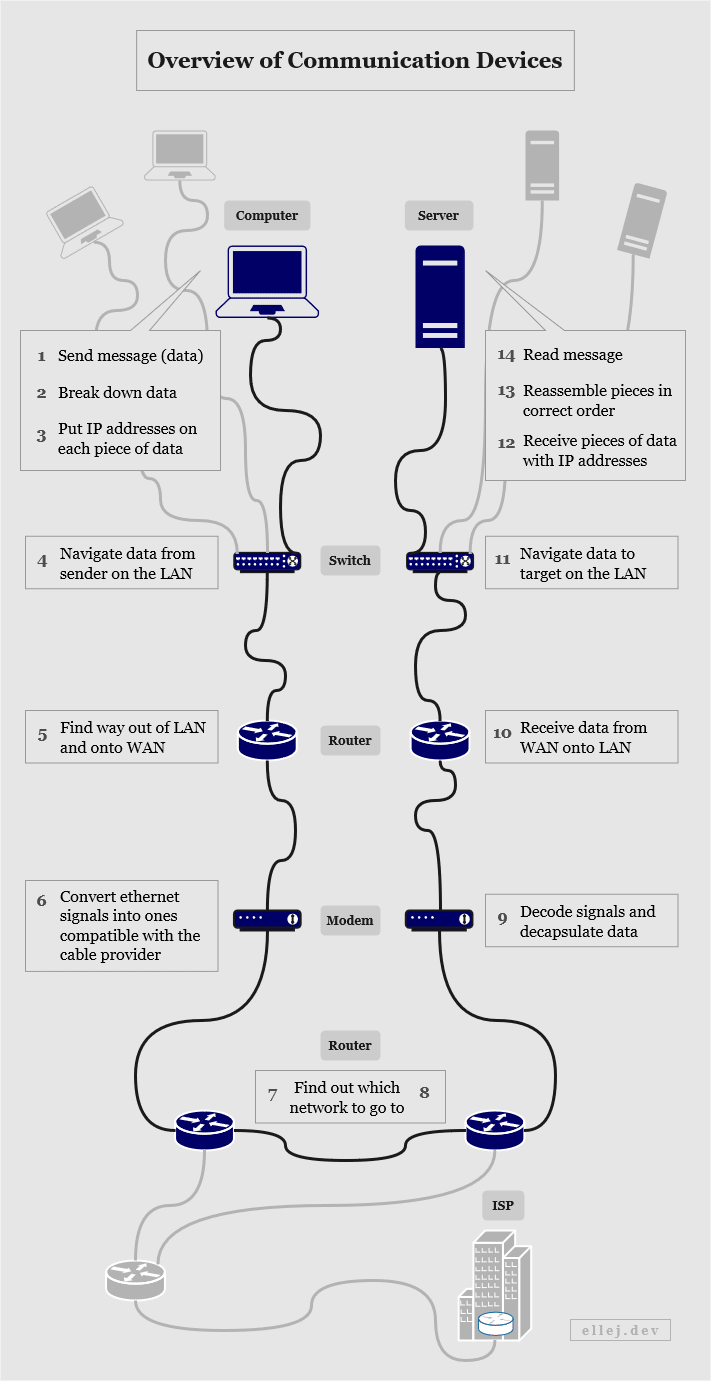
As we can see, the switch, router, and modem are three physically separate devices. Do you have all of these devices at home? Go check. You may have all three or you may have only one. In modern home network devices, those three components often exist in the same device. Although, they still follow the same logical flow as illustrated.
The computer on Step 1 connects to the switch via an Ethernet cable. While reading this article, are you connected to the Internet via a cable or WiFi right now? If you are connected using WiFi, your wireless access point device acts as both the switch and the router. When connecting to the WiFi, your computer behaves in the same way as if you were using a cable.
Here the server shares the same Internet Service Provider as you, but what if you are talking to a server on a different continent? Amazingly, they travel along hair-thin wires across the ocean floor clustered together with plenty others.
What is the Internet? (An Analogy)
Once upon a time, people used to write actual letters, put it in a mailbox, and wait for the postal service to have it delivered. But what transpires here is actually a clear step-by-step process on how to get the letter from address A to address B.
Let’s divide these steps into four layers and follow what happens with the letter. Starting at the top layer (Layer 4), Person A writes the letter and looks up the address of Person B and adds that to the letter. Person A then puts it in a mailbox after which the postal service picks it up and verifies that the letter can be received at the specified address (Layer 3). If something is wrong with the address, the letter will be returned to Person A. The postal service then finds out the best location to transport the letter to next (it might be an airport in order to get to one of their other service locations in another city) (Layer 2). They find out how to get to that location and use a truck to transport it within the city (Layer 1).
Once arrived in the correct city, a truck picks up the letter and drives it to the appropriate postal service location (Layer 1) where they look at the destination address (now being the one stated on the letter) (Layer 2) and pass it on to the section that will be responsible for transporting it to Person B (Layer 3). Once delivered in the same condition as it was sent, Person B opens the letter and reads it (Layer 4).
Having seen the diagram in the previous section illustrating the devices used in the communication flow, can you see a resemblance to the postal service analogy? Can you identify which layer(s) the devices belong to? I’ll leave that to you to figure out.
So, as we can see, in order to communicate properly we need to follow certain rules that specify how to send and receive a message. Moreover, we also need to know where the message is coming from and going to by using unique addresses for all locations visited in between. If every postal service on Earth uses these rules then everyone can communicate with each other. This is the basis of how the Internet works, by connecting networks (homes, cities, or countries) around the world speaking the same universal language which is the TCP/IP protocol suite--the practical rules for network communication (see next section).
What is the Internet? (For Real)
Rules that describe with specificity how to handle and transfer data is called a protocol. Transferring data from one place (or layer) to another requires the use of a particular protocol. If that data needs to be transferred to yet another layer then a different protocol may be used. Having a collection of protocols forms a protocol suite that in turn determines how and in what order the layers (the ones using the protocols) can send data between each other.
For instance, Layer A may only be able to transfer data to Layer B using Protocol 1 or Protocol 2, while Layer B only is able to transfer data to Layer C using Protocol 3 or Protocol 4. Hence, the data is transferred only one layer at a time since Layer A cannot communicate directly with Layer C, it only knows how to talk to Layer B.
To only be able to send data one layer at a time is a good thing because it reduces the responsibility at each layer. Think of the postal service analogy in the previous section. As the sender of the letter, I only want to know how to get the letter from my home to the mailbox (and how to write a correct address). How the letter arrives and everything that happens in between is none of my concern. Having less responsibility at each step makes it more organized and manageable.
Well then, what is the Internet? The protocols used when you type a URL and press enter are network protocols that are collectively called the TCP/IP protocol suite (also referred to as a stack or model). Internally on your computer as well as in your home, this stack is used to process and transfer data. If you have multiple devices at home communicating, they are on the same local area network (LAN). If you are chatting with your neighbor, his/her LAN and your LAN are on the same wide area network (WAN) which also uses the TCP/IP stack. So when multiple networks are connected using devices that implement this particular stack you have what is famously known as the Internet. The standards for the layers and protocols are defined by the engineers in the Internet Engineering Task Force (IETF).
A quick side note is that the World Wide Web is sometimes used interchangeably with the Internet, but that is a false assumption. The World Wide Web is a collection of resources (e.g. the index.html file served as the homepage of ellej.dev) that makes use of the Internet and specific protocols in the TCP/IP stack in order to link them together.
The TCP/IP Protocol Suite
The collective name of this suite comes from two of the several protocols used herein: TCP (Transmission Control Protocol) and IP (Internet Protocol). But as mentioned, this suite consists of many more protocols as we will see now.
Protocols are used to handle and transfer data between layers. There are four layers in this model:
- Layer 1: Link (also referred to as Physical, Data Link, or Network Access)
- Layer 2: Internet (also referred to as Network)
- Layer 3: Transport
- Layer 4: Application
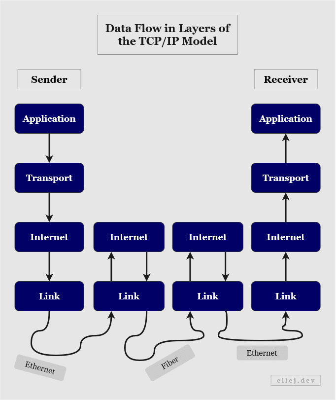
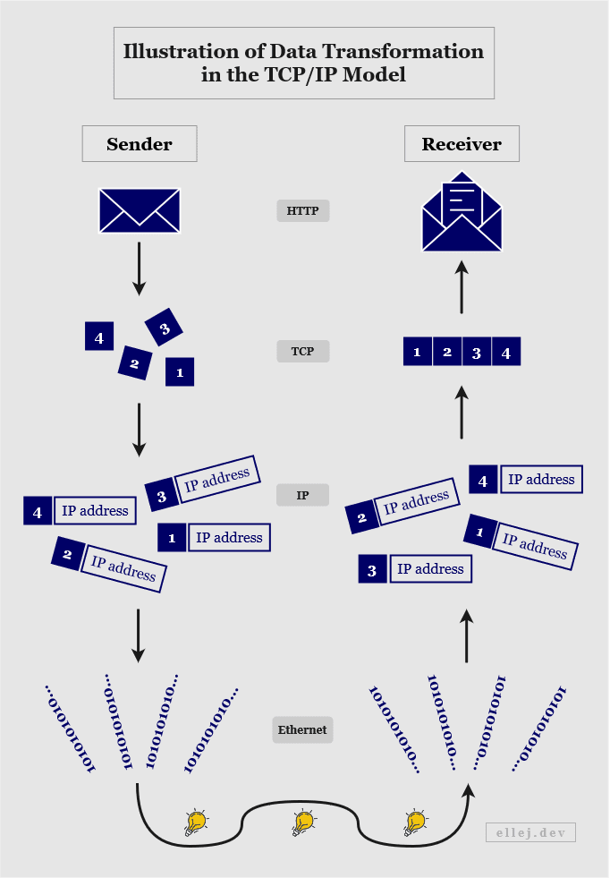
This clearly shows the flow from one layer to the next and, as noted by the arrows, how data is sent from the top, transferred down to the bottom layer, received by the bottom layer somewhere else, and finally transferred to the top layer on the receiving end.
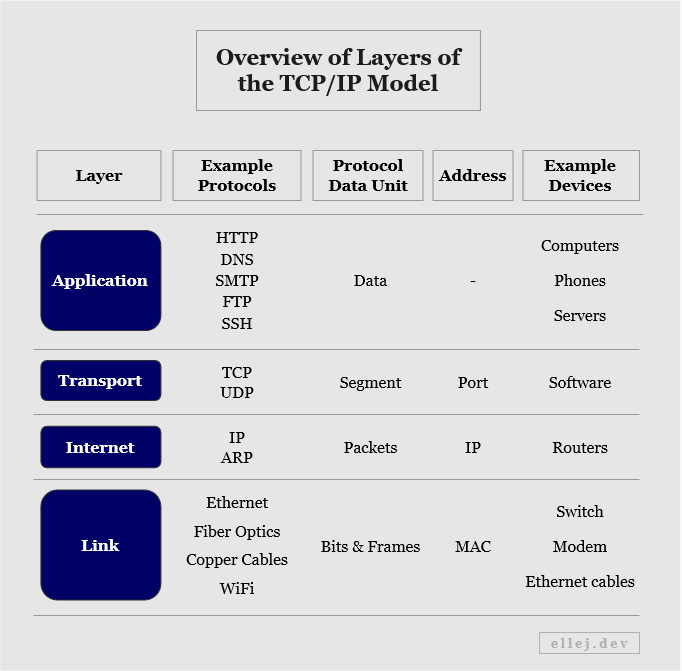
Each layer serves a different purpose and has certain protocols that can be used. They also manage addresses differently (using different units) and once the data arrives at a certain layer, that single piece of data is transformed into another protocol data unit, or PDU (see below).
Layer 1: The Link Layer
The link layer is the bottom layer and is, thus, the closest to the hardware. It is responsible for the communication within the local network, finds the physical device on the network, and connects with the other physical material such as cables and connectors. This is why it is sometimes called the physical layer.
The physical material (e.g. Ethernet cables) transmits the data to another host through electrical signals, so the link layer is also responsible for converting these signals into bits (ones and zeros). The physical device itself is uniquely identified by a Media Access Control (MAC) address. Most often Ethernet is used as the protocol, but other protocols include WiFi and Fiber Optics.
Layer 2: The Internet Layer
The Internet layer defines the actual network-to-network communication and handles routing over the network. It is also responsible for finding the shortest path to the destination network. As we could see in an earlier diagram showing the devices involved, the data, or packets as they are called in this layer, may pass through multiple routers (alternating between the link layer and Internet layer) before reaching your router at home.
The packets arriving here are assigned IP addresses and decisions made at this level are based on these addresses. Some protocols used are IP (IPv4 and IPv6) and Address Resolution Protocol (ARP).
Layer 3: The Transport Layer
The transport layer is responsible for the end-to-end delivery; meaning, it transports data from and to the actual program on the machine that needs it. If transferring the data to the layer below (the Internet layer) the data segment is first divided into separate packets in order to make it more manageable. If transferring the data to the layer above (the application layer) the packets are first put back together in the correct order.
In the postal service analogy it would have been a bit strange to include this breakdown of data, but to better depict what actually happens, the letter would have been torn apart into separate pieces along the way, each given a number signifying in what order to put them back together, and then reassembled looking exactly like it did when you sent it.
Segments are transported using TCP (for reliable but slower connections) or UDP (User Datagram Protocol) (for unreliable but faster connections) and use ports as addresses ranging from 0 to 65,535.
Layer 4: The Application Layer
The application layer allows software applications to interact with the network. When typing a URL address in your web browser, the browser acts as the application layer and may use the Hypertext Transfer Protocol (HTTP). By default, when typing http:// in front of the domain name (or :80 after it), it will contact the layer below (the transport layer) and say that the message should go to port 80, whereas if using the HTTP Secure (HTTPS) protocol by typing https:// (or :443 after the domain name) the address will be port 443.
Applications used for sending and receiving emails also apply to this layer and there are many more protocols used here such as Secure Shell (SSH), Post Office Protocol (POP3), File Transfer Protocol (FTP), Simple Mail Transfer Protocol (SMTP), and Domain Name System (DNS) when translating domain names to IP addresses.
Illustrative Summary of Layers
Finding Out Which Device to Send the Data To
So far we have learned that devices can communicate with each other by following certain network protocols and that the message travels from layer to layer where different purposes are served. We also just saw that each layer uses different addresses (such as port, IP, and MAC). So in order for the data to be able to reach the destination address, all layers (except the application layer) need to provide that corresponding value. Similarly, in order to be able to respond to the message, the source address also needs to be included at each layer.
Think back to the postal service analogy. If the letter arrives to whomever you wrote it to, but that person has no idea who sent it, don’t hold your breath getting a letter back any time soon. Similarly, if the letter needs to be returned to you for whatever reason, you would need to put your address (the source) on it as well.
Each of the four layers have what are known as headers. A header is a section of information (read by the computer as ones and zeros) where the sender can add details needed by the receiver, e.g. the source and destination addresses as well as other pieces of information. So when the user sends data in the application layer by typing https://www.ellej.dev, that layer will add information to its header and along with the data pass it on to the layer below which in turn adds its own header (see below).
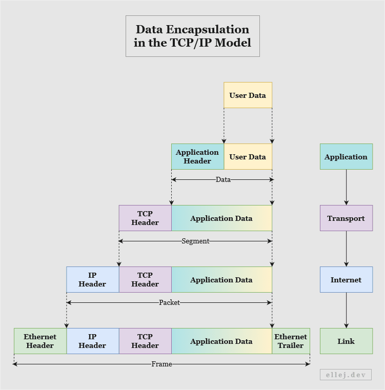
As the data approaches the hardware at the link layer it builds up by incrementally adding information needed by each layer at the receiving end. Thus, data flowing from top to bottom is called encapsulation of data. After travelling as electrical signals in copper cables, or as pulses of light in fiber cables, to the link layer on the receiving end, the data is decapsulated. Hence, data flowing upward is called decapsulation.
The diagram below shows a small part (source and destination) of the headers at layer 1-3, using example addresses. Notice how, when the server responds, the source and destination address values are swapped, turning the server into the source and your computer (the client) into the destination.
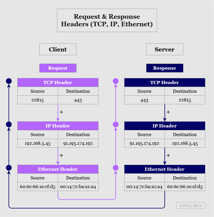
Thus, when typing a URL and pressing Enter, the TCP addresses (a.k.a. ports) of both the source and the destination are added to the TCP header. The IP addresses and Ethernet addresses (a.k.a. MAC) are then similarly added since each determine where to go in each layer. Once the receiving end has decapsulated the data upward and navigated it to the correct destination, it responds (e.g. with website data) by adding your browser's addresses to the destination fields.
But how did we know these addresses in the first place? I briefly mentioned that when using HTTP or HTTPS, port 80 or port 443 respectively will be used as the destination in the TCP header. But what about the IP address? The application layer has a protocol called DNS which is used to ask a DNS server to translate the domain name of a website to its IP address (this will be explained in a later section). So your computer first asked another server, got the IP, then put that address on the IP header.
However, the IP address itself does not say which actual device should receive the message. It only uniquely identifies which connection on a network the message is for, but with that unique connection we can find out the last piece of information (the physical, or MAC, address).
The link layer that connects multiple devices, such as a switch in your home connecting everybody’s computers to the same local network, can be asked by the Internet layer, such as a router, to identify which of its connected devices that has a particular IP address. The link layer then broadcasts a message to every device asking “Who has got the IP address 192.168.1.2?” Whoever responds will respond with its corresponding MAC address and that address will subsequently be added to the header (see below).
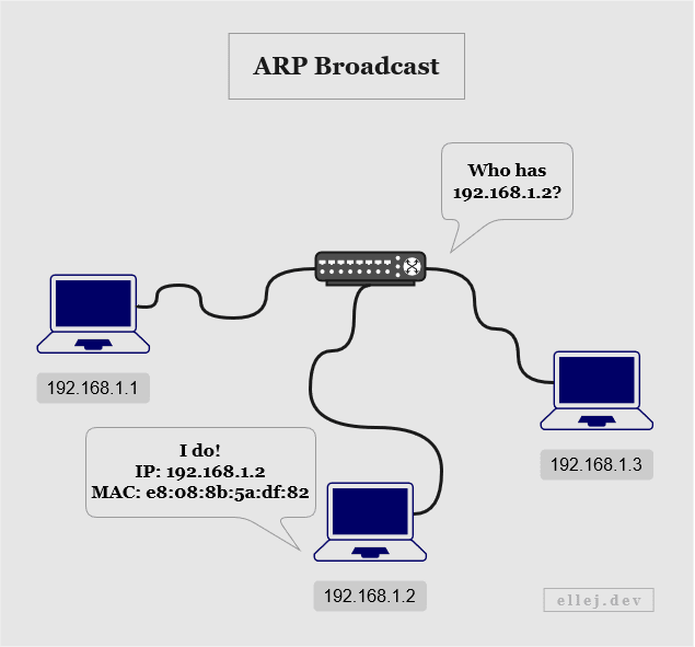
This is called ARP broadcasting since ARP (Address Resolution Protocol) is the protocol used for getting the physical, or MAC, address. One thing to note, however, is that an ARP broadcast may not always be needed if one has already been made at an earlier point in time since the MAC address is then added to the sender’s cache.
Have a look at the partial ARP and Ethernet headers below. The request starts at the Internet layer since it will eventually need to pass the target MAC address down to the link layer so that it can be added to the destination address field on the Ethernet header once the ARP broadcast is done.
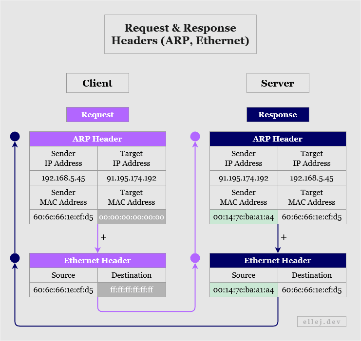
As you can see, in the request the target MAC address is unknown (indicated by the value 00:00:00:00:00:00), hence no destination address can be put in the Ethernet header (indicated by the value ff:ff:ff:ff:ff:ff). Once all connected devices receive this message and decapsulate it up to the Internet layer, the device matching the target IP address will respond by adding its own IP and MAC addresses as the sender, and the addresses of the one it is responding to as the target.
Since we now have the MAC address of the destination, the data can continue its path to the next location (or next hop since the data is “hopping” from one device to the next). The number of hops needed to get from one router to various destinations are stored in their so-called routing tables (which are continually added to as they communicate with more routers). This, along with other information about adjacent routers, is one of the factors that routers base their decisions on when forwarding data. (Kind of similar to using your GPS in the car. It tells you the shortest path, however it does not always mean shortest in terms of distance as some roads may have lower speed limits. Routers also take into account how fast the data can travel over the wire.)
Following the Data From Your Computer to the Server
Remember the diagram in the beginning showing all of the connected devices such as routers and switches? By now, you are hopefully a lot more familiar with the details of what actually happens with the message at each layer in which these devices are used, so let’s revisit this diagram with a more accurate sequence of events.
(The diagram assumes that the client, or computer, has already received the IP address of the destination from a separate DNS server.)
Pressing Enter
Knowing how the data gets transferred layer by layer from source to destination and vice versa, let’s zoom out and refocus our attention on what the very first diagram showed us. Namely, that when pressing enter the following five steps occur:
- Translate the domain name
- Establish a connection
- Encrypt the communication
- Request the resource
- Terminate the connection
Step 1: Translate the Domain Name (DNS Query)
The domain name ellej.dev needs to be translated into an IP address so that all outgoing packets can be properly labeled according to the Internet Protocol. This is initiated at the application layer using the Domain Name System (DNS) protocol.
Your computer will start by making a DNS query. The first query will be to a DNS client on your operating system called a stub resolver. This stub resolver, which is used by the browser, passes on the query to a so-called recursive resolver (another DNS client) run by some network operator, which in turn queries additional authoritative name servers storing the actual DNS data (usually hosted by web hosting services or other providers of network servers).
When a response comes back with the IP address of the domain name initially queried, the IP address of the authoritative name server is also available in the header. Ideally, this means that we can verify that the IP address received is coming from the source that we expect it to come from. In other words, we want to be sure that the requested IP address is actually that of ellej.dev and not some malicious website. However, solely verifying the authenticity of the response based on the IP address of the sender is not secure since forging that data is quite easy. Thus, for added security features to the DNS protocol, DNSSEC (Domain Name System Security Extensions) is used.
DNSSEC utilizes what is known as asymmetric cryptography. The principle of the underlying encryption technique is that the sender encrypts the data with a key from the receiver (a public key), afterwhich the encrypted data is sent to the receiver who then decrypts it with a key only known to the receiver (a private key). This is the basis in end-to-end encrypted systems.
With this technique, a public-private key pair is generated and the owner of the DNS information encrypts that data with its private key. Since data encrypted with the private key can only be decrypted with the public key (and vice versa), the recursive resolver asking for the IP address of ellej.dev will get the owner’s public key and use it to decrypt the data. If the decryption succeeds, we can verify that the data sent came from the correct source since that source should be the sole keeper of the corresponding private key. (The fact that anyone with the public key can decrypt the data is not an issue since the purpose of this asymmetric encryption is not to make the IP address of the domain name private, but to validate the origin of its source.)
There is, however, still a security flaw in the above scenario. What if the resolver is using the public key of a malicious server and not the one it thinks it is using? If the malicious server encrypts an IP address leading to a malicious website and the resolver retains its public key (instead of the real owner’s public key), the resolver will successfully decrypt that response and, thus, assume that the response is valid. Consequently, DNSSEC adds yet another feature to DNS called a chain of trust.
A chain of trust is essentially a way of establishing trust for a public key. It is implemented by having the parent of the owner of the DNS data encrypt the public key of its child. So in order to access the public key, the resolver first needs to decrypt it using the parent’s public key. Again, that public key is also encrypted by its parent, so we need to traverse all the way up to the root (e.g. the owner of “.com” or “.org”) and start decrypting key after key. The idea is that if the resolver trusts the root, it can trust all of its children and grandchildren and so forth.
Step 2: Establish a Connection (TCP Handshake)
The Transmission Control Protocol (TCP) is so-called connection-oriented, meaning prior to the message being sent it first establishes a connection between the source and destination networks. This guarantees the delivery of the message (creates a reliable connection) and is done through a TCP 3-way handshake.
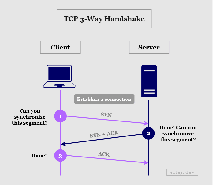
The handshake is initiated by the client (your computer) which sends a message (or segment) to the server with a TCP header containing a SYN flag. In previous sections, we only looked at the address fields on the header, but as mentioned, there are several other fields, one of which being a flag field. The SYN flag indicates that the client wants the server to synchronize a particular sequence number also included in the header. This sequence number will tell the server to track every segment starting from that number and will also allow the server’s transport layer to know in what order to reconstruct the data.
If the server is listening on the port that it was sent to, the segment will be received and the server replies with another segment containing a SYN and ACK flag in the TCP header. ACK implies that the server has acknowledged the client’s request (along with an acknowledgement number verifying synchronization). SYN is in this case the server’s request for the client to synchronize the sequence number returned by the server.
For the third and final handshake the client responds to the server with an ACK flag (and a verifying acknowledgement number), acknowledging the server’s response. Once completed, a connection is established and the transmission may begin.
Step 3: Encrypt the Communication (TLS Handshake)
Hypertext Transfer Protocol (HTTP) and Hypertext Transfer Protocol Secure (HTTPS) are protocols used in the application layer, as you know by now. With HTTP, data is transported unencrypted making it fully readable for anyone intercepting the traffic. In order to allow for a more secure way of using the Internet when dealing with sensitive data, but also for general privacy, a cryptographic protocol called Secure Socket Layer (SSL) was created. This protocol was meant to be used together with HTTP in order to encrypt the data, and collectively became known as HTTPS (also, HTTP Secure and HTTP Over SSL).
The cryptography used is based on the same technique as explained during Step 1 when using DNSSEC, namely asymmetric encryption (using private and public keys). Although, the difficulty of decrypting the data without the private key is only as high as the strength of the encryption algorithm. The algorithms used in SSL ultimately became too weak and the protocol has now been replaced with Transport Layer Security (TLS) which implements stronger algorithms.
So, in order for the client (your computer) to encrypt data that only the server can decrypt, it needs the server’s public key. This key is distributed through certificates, so the server needs to have an SSL certificate (it is still commonly referred to as SSL even though the actual protocol is TLS). When the client receives the certificate from the server it will verify it with the issuer of the certificate, also known as a certificate authority, or CA, and then use the public key to encrypt additional information that the server needs. This is known as a TLS handshake (see below).
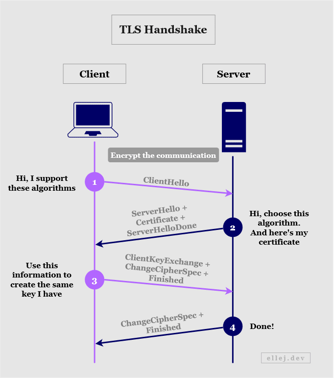
The following occurs:
- The client sends its TLS version and what algorithms it supports.
- The server sends the TLS version and algorithm to use, and its certificate.
- The client verifies the certificate and creates a new key based on information (called a secret) that the client has created. Using the public key from the certificate, the client encrypts the secret and sends it to the server.
- The server decrypts the secret with its private key and uses it to create the same key that the client also created.
Since both of them now have the same key, they can use that new key to encrypt and decrypt messages going back and forth. So from this point on, symmetric, rather than asymmetric, encryption is used.
Step 4: Request the Resource (HTTP Request)
Up until this point we have established a reliable connection and a way to send encrypted data. The client can now request the resource originally intended, i.e. the index.html file from the host of ellej.dev, using the HTTP protocol. (HTTP together with TLS is known as HTTPS.)
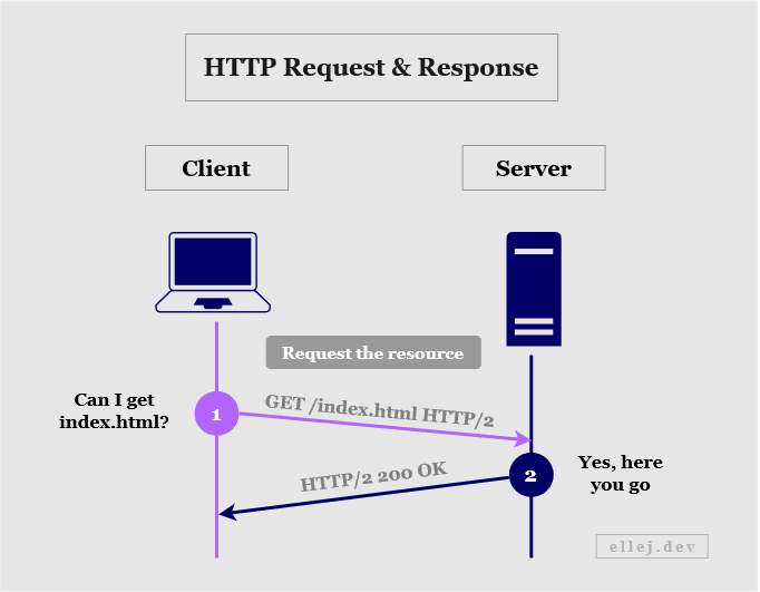
The client sends a request to get the resource using HTTP version 2 whereafter the server responds with a status code of 200, meaning “okay” (success), along with the body of the document (the HTML content). The browser understands HTML (Hypertext Markup Language) and renders it on your screen.
If the web page also contains other resources such as images or a file for styling the page, those also get requested in this step one by one (for HTTP version 2). If HTTP version 1.1 is used, a separate connection and HTTP request need to be made for each additional resource.
Step 5: Terminate the Connection (TCP Handshake)
Terminating the connection is quite similar to the handshake made when establishing the connection. In Step 2, the client and server did a TCP 3-way handshake, however in order to close the connection they need to make a TCP 4-way handshake because the connection needs to be terminated in both directions independently.
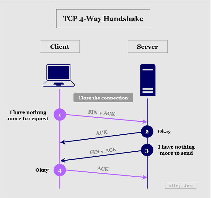
The following occurs:
- The client tells the server that it has no more data to send by including a FIN flag in the TCP header. The ACK flag (along with an acknowledgement and sequence number) let’s them know which connection to terminate.
- The server acknowledges the segment received (ACK) and sends a verifying acknowledgement number.
- The server tells the client that it has no more data to send (FIN) and let’s it know which connection to terminate (ACK).
- The client acknowledges the segment (ACK) and sends a verifying acknowledgement number.
And That’s the Beauty of the Internet
Great journey, huh? Having learned about many of the intricacies of how the Internet works, don’t you think it is amazing how a web page can be served to you just a few seconds after typing the URL and pressing enter? I know I sure do.
Stay Curious! :)
Comments powered by Talkyard.
Comments powered byTalkyard.